Piping Deadlegs: Design Them Out!
Turnaround Technical Talks
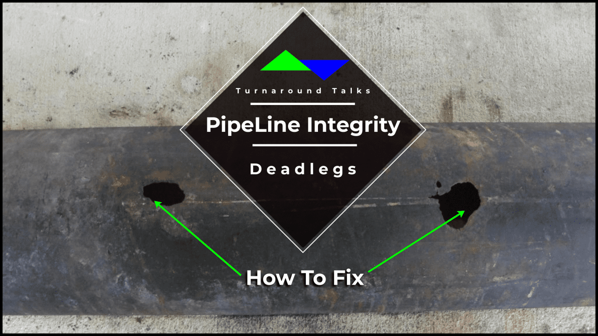
(Through-wall microbiologically induced corrosion (MIC) of a crude oil pipeline)
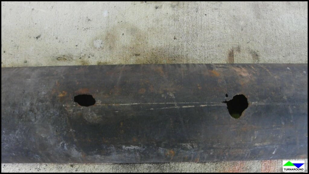
(Through-wall microbiologically induced corrosion (MIC) of a crude oil pipeline)
“I’ve always designed piping systems this way,” said the experienced salty piper as he shrugged off the inferior designer’s comments regarding the piping layout he had created. The process piping design and layout profession have existed for a considerable time in the United States. After all this time, various practices in the process piping industry have persisted. If it has worked all these years, then why reinvent the wheel? The pipe is still round, and things still flow downhill. Nonetheless, industrial process plants in the U.S. are reaching or exceeding their expected useful life with countless lessons learned from the catastrophic events and near misses surrounding the process piping industry.
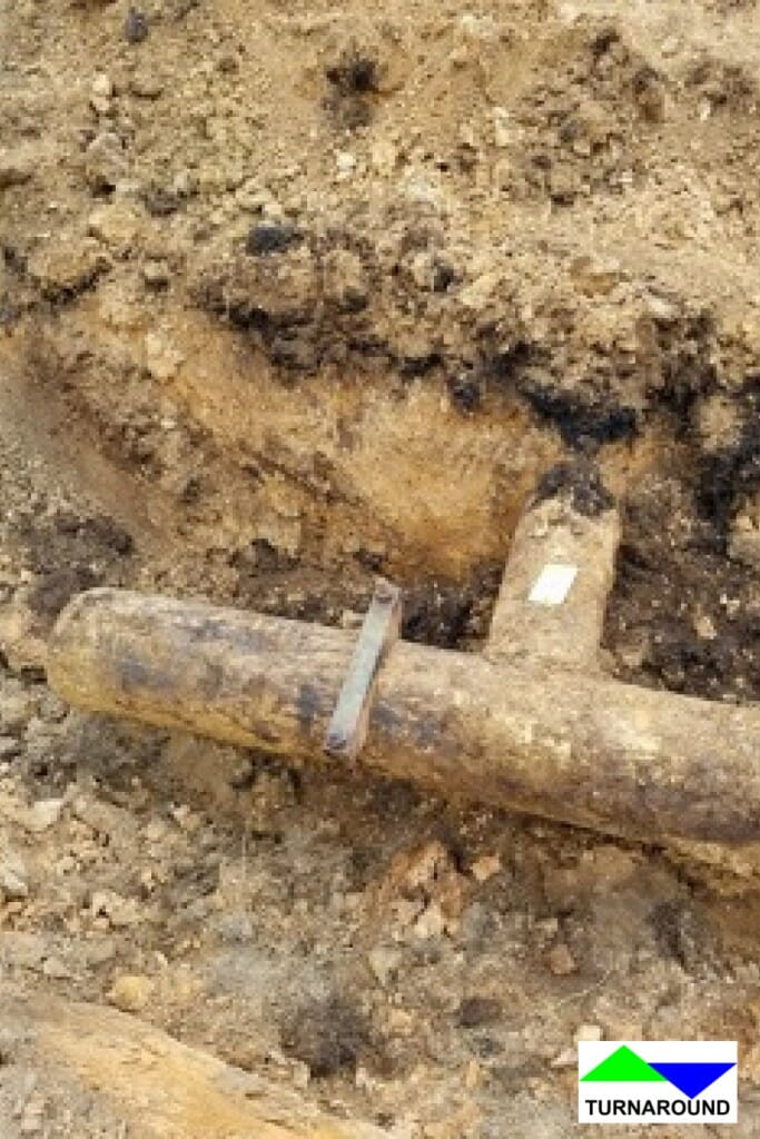
(Underground crude oil pipeline leak at piping branch stub-in connection)
The ASME B31.3 Process Piping standard is typically the code of construction for process piping systems (ASME). Once process piping is constructed and placed into service the American Petroleum Institute’s (API) 570 Piping Inspection Code regulates the in-service piping system. API defines deadlegs as “Components of a piping system that normally have no significant flow. Some examples include blanked branches, lines with normally closed block valves, lines with one end blanked, pressurized dummy support legs, stagnant control valve bypass piping, spare pump piping, level bridles, relief valve inlet, and outlet header piping, pump trim bypass lines, high-point vents, sample points, drains, bleeders, and instrument connections,” while the ASME B31.3 standard does not define a piping deadleg (API).
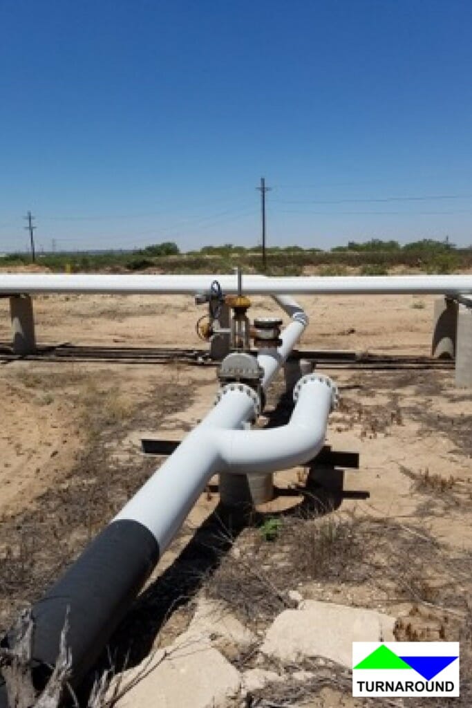
Deadleg in an existing piping system for a future tie-in that was never utilized
All too often, a piping designer has little to no interaction with the project after final construction deliverables are turned over to the client. Outside of feedback received in the form of a Request for Information (RFI) from the field during construction, most piping designers working on large capital projects never see their designs come to fruition. While unfortunately, the reliability inspector or engineer responsible for the asset’s performance never puts their eyes on the design until it’s mechanically complete. The disconnect between the owner’s engineering team and the outside engineering firm’s design team has never been greater now that remote work allows project teams to be scattered across the world. Lamenting this divide is the realization that large capital expenditure projects are often managed by a specialized owner’s engineering team outside of the local project site, contributing to site-specific requests going unheard.
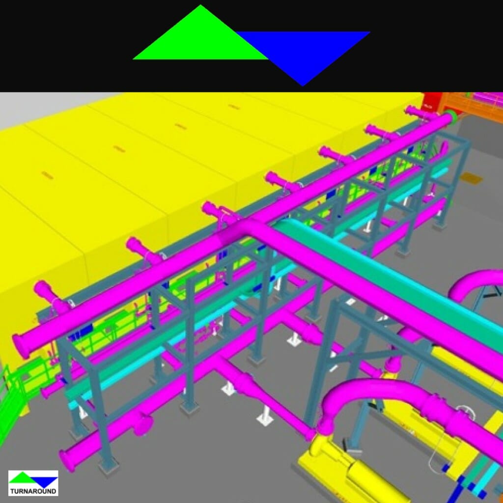
New piping design incorporating deadlegs at the end of the piping headers
Inner pipe wall look at through-wall MIC corrosion
Deadlegs cannot be avoided in their entirety. However, with proper equipment siting and piping layout, many deadlegs can be eliminated early in the design phase. Onset deterioration in a deadleg can be rapid, with elevated corrosion rates and contamination attributed to low or no flow that can eventually lead to loss of primary containment. Deadlegs must be located on piping circuit inspection isometric drawings to facilitate consistent wall thickness measurements and monitor the location’s mechanical integrity. Pictured to the left is a section of a carbon steel crude oil pipeline deadleg that experienced through-wall localized thinning due to microbiologically-induced corrosion (MIC) in less than two years of being placed in service. At the additional operating expense, biocides and corrosion inhibitors can be deployed in conjunction with increased condition monitoring to mitigate some uncertainties in piping circuits containing deadlegs. Metallurgical upgrades at points of low or no flow can offer higher corrosion resistance and extended life. Vents and drains also experience low or no flow and are classified as deadlegs. The piping designer must understand the project’s pressure testing plan to provide a purpose-built application. The necessity for pressure testing vents and drains depends on whether the piping circuit will be pressure tested as a system in-situ or in the shop as independent spools. Shop-tested spools rarely require pressure-testing vents and drain since testing blinds or caps can be utilized. Pressure testing in the field requires high-point vents and low-point drains are located at all high and low points in the piping system. A good designer must balance system testing and operating necessities with long-term maintenance costs. One Condition Monitoring Location (CML) can add thousands to the long-term cost of an asset, and a single deadleg can contain multiple CMLs.
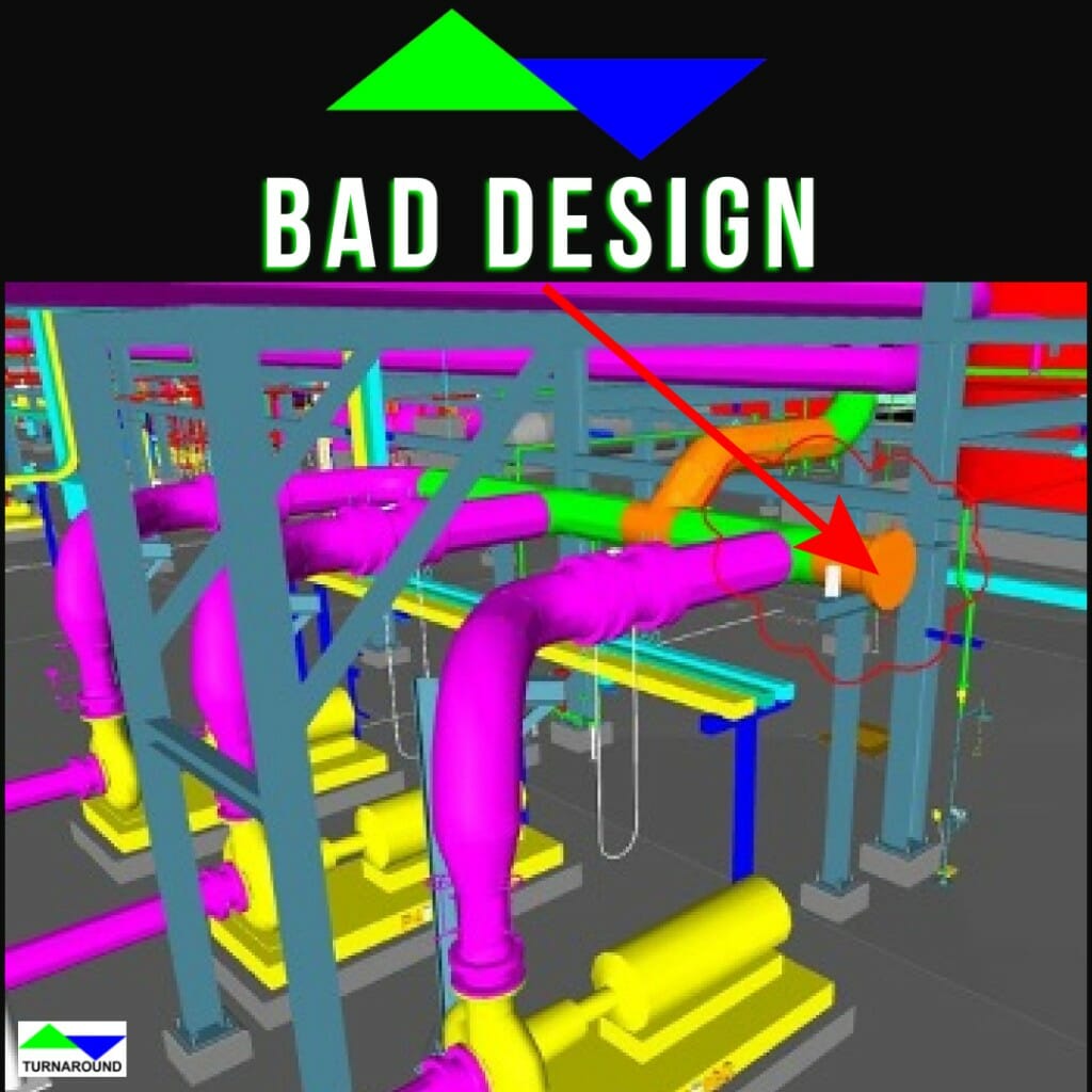
Bad piping design practice utilizing deadlegs at header ends
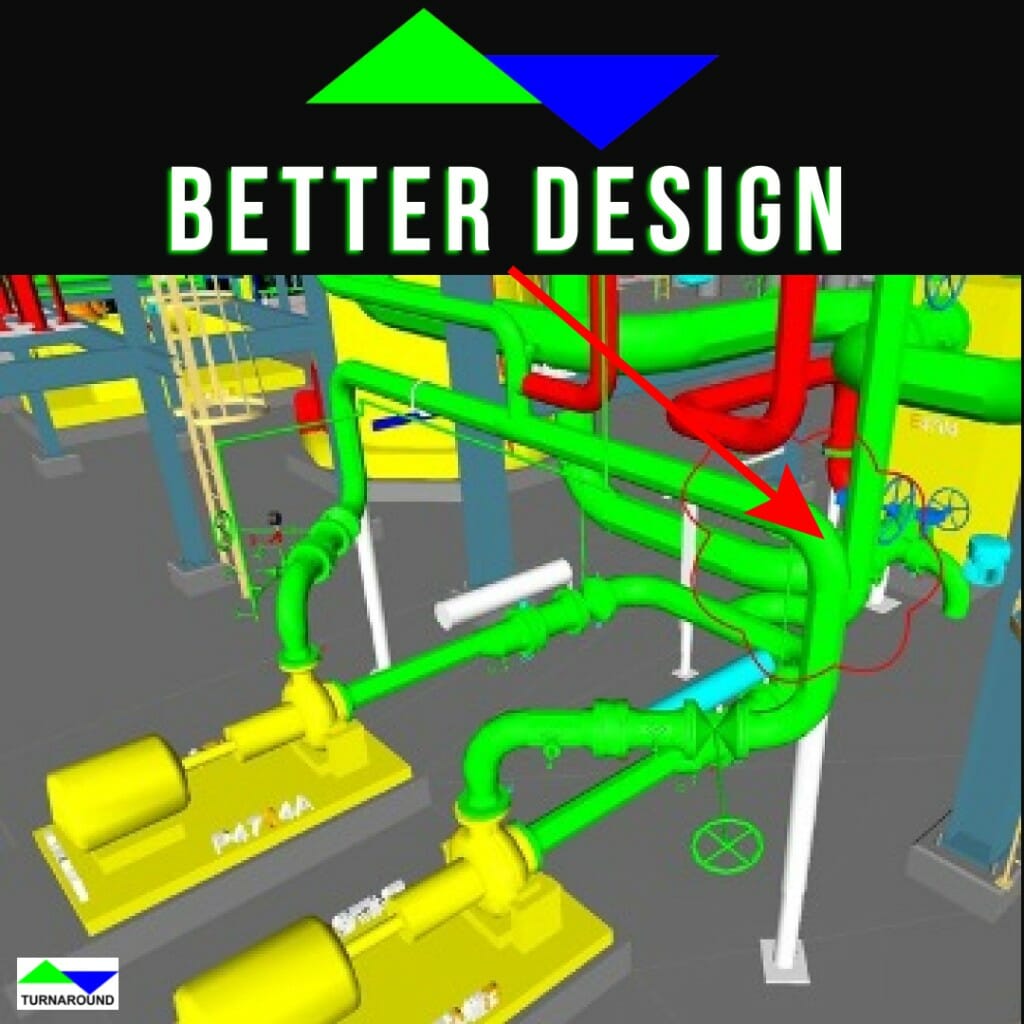
Good piping design practice without deadlegs at header ends
Piping headers should be terminated with an elbow at a change of direction unless a clean-out is required for maintenance.
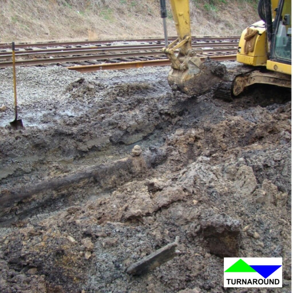
Underground pipeline leak due to corroded deadleg at a plugged branch connection
Piping demolition projects should not create or leave a deadleg in place. Instead, remove the affected section of the main piping header for a first-time-right approach that will save you money and trouble in the long run.
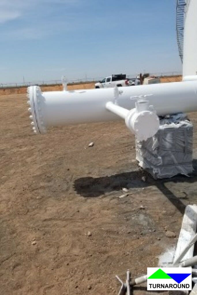
Piping manifold with a connection for a future tie-in
It is not advised to leave future connections in a piping system, unless necessary. Make provisions to cut in a new fitting for future branch connections. There are way too many “future” connections corroding in the field.
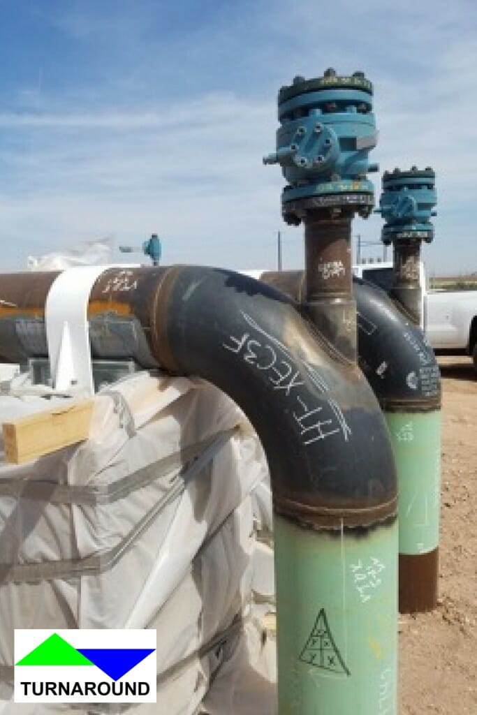
Pipeline drain-up connections
Eliminate operational and pressure testing vents and drains from the design when possible. Utilize integrally reinforced forged combination fittings for vents and drains when necessary, such as a valvolet. At pressure instrument connections, consider installing manifolds with integral isolation and vent valves, such as a 3-valve manifold, directly on the piping header o-let, without a piping nipple and root valve, when allowed by the piping specification.

IFR Drawing Stamp
An owner/operator’s best defense against deadlegs and design inconsistencies in their new construction project is a detailed set of design guidelines clearly stating minimum expectations, to be referenced in whole on the project engineering purchase order. The opportunity to ascertain whether the proposed design conforms to written practices lies within the detailed-design review process. The 30% design review is the appropriate time to comment on major changes required to the conceptual design. Validate the incorporation of comments from the 30% review and approve the design during the 60% review. The 90% review should be a quick check of the final deliverables, confirming that all review comments were captured. To minimize major changes from occurring after the 60% milestone, the client’s project sponsor must set expectations for the minimum level of detail required for deliverables at each review stage. The review packages and 3D model should be submitted to the project stakeholders before the scheduled group review meeting to allow adequate time for a thorough independent check. Project stakeholders must make time to extensively review the 30% design package and should come prepared with their comments to the group design review meeting. The project stakeholder roster should include decision-makers from not only operations, but maintenance, and reliability departments as well. A collaborative relationship between the project designers and the asset’s reliability specialist provides continuous improvements and leads to a refined design.
American Society of Mechanical Engineers (ASME). (2020). In Process Piping: ASME Code for Pressure Piping, B31. definitions
American Petroleum Institute (API). (2009). In Piping Inspection Code: In-service Inspection, Rating, Repair, and Alteration of Piping Systems. 3.1.16, P. 5
Author: Keith Grimes – Let’s Connect!
Turnaround Technical, LLC

